| Theories and Techniques of Oral Implantology (vol.2) (published 1970) | Dr. Leonard I. Linkow |
|
|
Next Page |
| This is an archival HTML version of this book originally hosted here in 2006. The HTML may not display well on modern browsers. Please view the modern PDF Version for a better viewing experience. |
648 Theories and techniques of oral implantology
An intraoral x-ray, which included the floor of the maxillary sinus and the apex of the second bicuspid tooth, was taken (Fig. 15-58). The scalloped template with its two anterior bicuspid crowns was then removed.
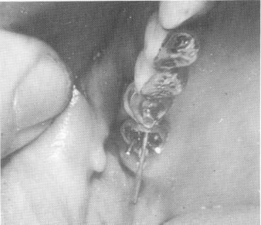
Fig. 15-61. The pin implants were then driven through the template one by one, circumventing the maxillary sinus in an anteroposterior direction.
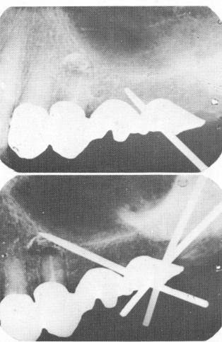
Fig. 15-62. A, The first pin was radiographed a number of times in order to be certain that it would be driven between the tooth apex and the floor of the sinus. B, The periapical radiograph showing the three pins in their proper positions. The ends protruding through the template were cut short so that they would not interfere with the fitting of the superstructure. (From Linkow, L. I.: Atypical implantations for anatomically contraindicated situations, Dent. Concepts, Fall, 1967.)
The positions of the three triplant pin holes to be made in the template were determined from the x-rays and were made with a No. 557 fissure bur. The holes were angled in the template in the same direction as the implant pins were to be directed. The holes were made large enough to avoid interference with the angulation of the pins. Otherwise the template, pins, or both could have become distorted, causing constant pressure in the area.
To make room for the triplant pin, the apicoectomy was then performed. Great care was taken not to injure the floor of the sinus (Fig. 15-59). The bicuspid crowns with the extending template were cemented with hard cement over the bicuspid preparations (Fig. 15-60). The implant pins were slowly driven through the template and deep in-
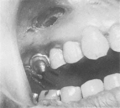
Fig. 15-63. The pin implants extended through the scalloped template. High up in the maxillary tissue is seen the exposed bone and area where the apicoectomy was per-formed.
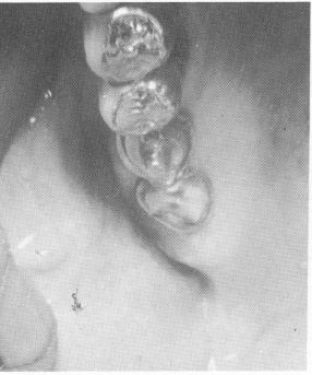
Fig. 15-64. The three pins were locked to each other and to the template with acrylic.
A
B
|
|
Page 648 |
Next Page |
|
Copyright warning: This information is presented here for free for anyone to study online. We own exclusive internet copyrights on all content presented on this website. We use sophisticated technology to identify and legally close down websites that reproduce copyrighted content without permission - so please don’t do it.
|