| Theories and Techniques of Oral Implantology (vol.2) (published 1970) | Dr. Leonard I. Linkow |
|
|
Next Page |
| This is an archival HTML version of this book originally hosted here in 2006. The HTML may not display well on modern browsers. Please view the modern PDF Version for a better viewing experience. |
646 Theories and techniques of oral implantology
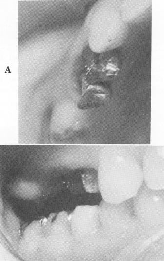
crowns. Additionally, and most importantly, the mucoperiosteal tissue along the alveolar crest posterior to the second bicuspid tooth was so thick that it was in direct contact with the somewhat extruded lower right molar tooth (Fig. 15-51) . This made it impossible to place any teeth in the area without treatment.
On the first operative visit, the short crowns of both maxillary bicuspid teeth were lengthened by electrosurgically removing the soft tissue. The two teeth were then prepared for veneer crown restorations. The thick and protruding fibromucosal tissue extending below the alveolar ridge in the posterior edentulous area was reduced almost to the under-lying bone with a scapel and electrosurgery (Fig. 15-52). The partially exfoliated mandibular molar was also reduced occlusally by judicious grinding of the gold inlay covering it (Fig. 15-53) .
Copper band impressions, a wax interocclusal record of centric relation, a plaster index, and an alginate (irreversible hydrocolloid) impression of the lower jaw were taken of the bicuspid teeth. Temporary crown forms were placed over the pre-pared abutment teeth, and the patient was dismissed.
Fig. 15-54. The tissue as it appeared 2 weeks after surgery. Enough space was created to include an upper implant and second molar.
To allow adequate healing of the treated soft tissues, almost 2 weeks lapsed between visits (Fig. 15-54) . Then the temporary crown forms were rernoved, and the veneer castings were tried over the maxillary bicuspid teeth. All necessary occlusal and gingival adjustments were made.
A wax interocclusal record of centric relation and a plaster index, which included the two crowns as well as the entire edentulous area, were taken. The index was then articulated with the previously poured lower stone model, and from this master
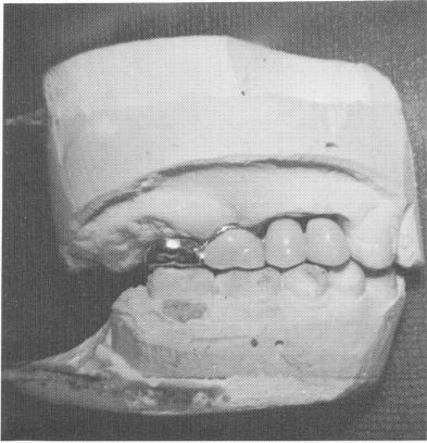
Fig. 15-55. A prefabricated unilateral four-unit veneer type bridge seen on the model.
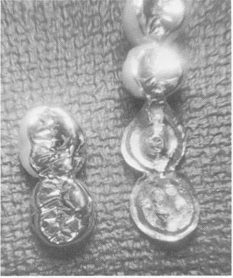
Fig. 15-56. Posteriorly, a scalloped template and two-unit superstructure are seen.
B
|
|
Page 646 |
Next Page |
|
Copyright warning: This information is presented here for free for anyone to study online. We own exclusive internet copyrights on all content presented on this website. We use sophisticated technology to identify and legally close down websites that reproduce copyrighted content without permission - so please don’t do it.
|