| Theories and Techniques of Oral Implantology (vol.2) (published 1970) | Dr. Leonard I. Linkow |
|
|
Next Page |
| This is an archival HTML version of this book originally hosted here in 2006. The HTML may not display well on modern browsers. Please view the modern PDF Version for a better viewing experience. |
600 Theories and techniques of oral implantology
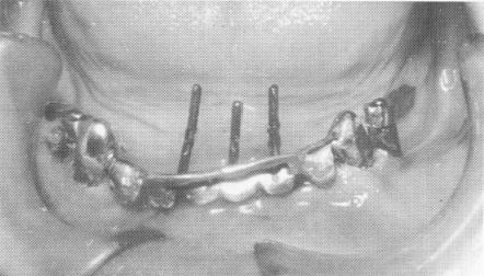
Fig. 13-43. Three pin type implants were then drilled through predetermined holes made in the anterior portion of the template. They were driven as deeply as possible, ending on top of the cortical plate of bone that lay at the inferior border of the mandible.
Fig. 13-44. The excess length of the extending pin implants was cut away so that the pins could be bent underneath the inverted U-shaped bar extending superiorly from the scalloped template.
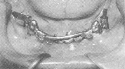
Fig. 13-45. The pins were then bent so that they fell within the confines of the inverted U-shaped bar.
13-4b. The pins were fused to each other and locked between the inverted bar and template with cold cure acrylic. When the acrylic hardened it was prepared so that no undercuts remained. The vertical acrylic bar was then polished.
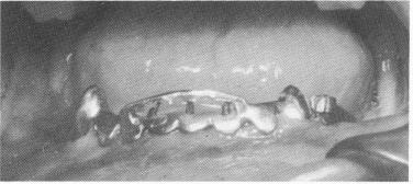
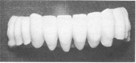
Fig. 13-47. The acrylic full arch splint. It can be worn either with temporary cement or with no cement at all, allowing it to be taken off and placed back on at will.
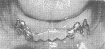
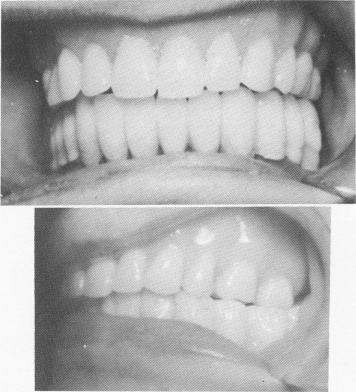
Fig. 13-48. The splint in position.
template (Fig. 13-43). These pins were extended deep into the bone, down to the cortical plate in the inferior portion of the mandible. The three pins were shortened to the height of the horizontal portion of the U-shaped bar (Fig. 13-44) and then bent anteriorly so that they fitted flush to, but underneath, the horizontal bar (Fig. 13-45). The three pins were fused together (using the brush-on technique) and to the entire inverted U-shaped bar with cold cure acrylic, thereby becoming an integral part of the template (Fig. 13-46). An all-acrylicover-gold full arch denture was then processed (Fig. 13-47). The bridge was used as a fixed removable denture and was set buccal to the mylohyoid ridge, instead of on it, to avoid further pain (Fig. 13-48). A Panorex shows the implants and prosthesis (Fig. 13-49) .
For a patient requiring a unilateral fixed partial denture, it was necessary to avoid using previously jacketed anterior teeth. Therefore an endodontic pin implant was planned to stabilize an upper left cuspid
|
|
Page 600 |
Next Page |
|
Copyright warning: This information is presented here for free for anyone to study online. We own exclusive internet copyrights on all content presented on this website. We use sophisticated technology to identify and legally close down websites that reproduce copyrighted content without permission - so please don’t do it.
|