| Theories and Techniques of Oral Implantology (vol.1) (published 1970) | Dr. Leonard I. Linkow |
|
|
Next Page |
| This is an archival HTML version of this book originally hosted here in 2006. The HTML may not display well on modern browsers. Please view the modern PDF Version for a better viewing experience. |
158 Theories and techniques of oral implantology
emerges through the soft tissue. Its roundness is less irritating than a square or hexagonal shaft. The uppermost part, which will bear the prosthesis, may be internally threaded so that the prosthesis can be screwed into it.
These modifications underwent a great deal of variation. The vent was enlarged and reduced in size; it was lengthened and shortened. The spiraled portion was reduced apically from the early model shown in Fig. 5-44. Enough variation is inherent in the design so that a vent-plant suitable for almost any site can be utilized (Fig. 5-45).
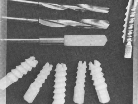
Another approach to encourage the close condensation of bone around an implant has been taken by the Swiss, Sarni Sandhaus, who has been using synthetic sapphire, or aluminum oxide, implants (Fig. 5-46) . Sandhaus claims that this material is even less irritating to the tissues than the commonly
used alloys. Thus bone grows right up to this implant, without the formation of a false periodontal membrane. Linkow feels that instead of being an advantage, this feature is actually a disadvantage. The majority of evidence so far indicates that with-out some kind of "periodontal" membrane to transmit the forces, bone resorption will usually be the end result.
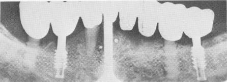
Testing Sandhaus' claim that the bone's fusion to an implant may be desirable, Linkow coated his vent-plants by implosion with synthetic sapphire (Fig. 5-47). Radiographs of the implanted designs are confusing (Fig. 5-48). Radiolucent areas appear around the sapphire implants but not around the vent-plants. The cause of this has not been deter-mined. Perhaps radiolucent areas appear around Sandhaus' implants because they are too broad, particularly at the alveolar crest. Because Sandhaus
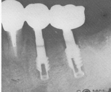
Fig. 5-45. By lengthening the shaft and moving the widest portion down, a deep shelf of bone can grow over the spirals. Here the implants are shown immediately after insertion. Note that the self-tapping feature permits a mini-mum of damage to the site: the spiraled portion is surrounded by bone.
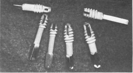
Fig. 5-47. Vent-plants coated with synthetic sapphire.
Fig. 5-46. Sandhaus' synthetic sapphire (aluminum oxide) implants, shown with their drills and taps. (Courtesy S. Sandhaus.)
Fig. 5-48. Vent-plants and sapphire implants used together. Note bone breakdown around the sapphire implants.
|
|
Page 158 |
Next Page |
|
Copyright warning: This information is presented here for free for anyone to study online. We own exclusive internet copyrights on all content presented on this website. We use sophisticated technology to identify and legally close down websites that reproduce copyrighted content without permission - so please don’t do it.
|