| Theories and Techniques of Oral Implantology (vol.1) (published 1970) | Dr. Leonard I. Linkow |
|
|
Next Page |
| This is an archival HTML version of this book originally hosted here in 2006. The HTML may not display well on modern browsers. Please view the modern PDF Version for a better viewing experience. |
Operative tips 267
further into the bone; and a final driving chuck, which engages only the tip of the implant so that all of the remaining portion can be driven deeply into the bone.
When the time comes for preparing the acrylic core, a fissure bur and tapered diamond stone are also needed.
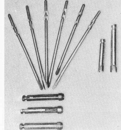
Fig. 7-21. American version of the double-lock pin implant with various chucks.
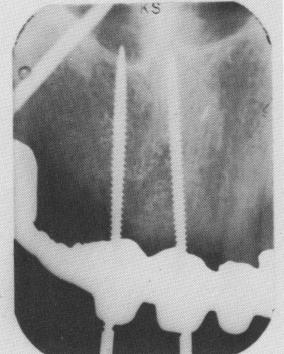
Fig. 7-22. Threaded pin implant. (Courtesy I. Lew.)
Pins. There are two types of pins, the French ones of Scialom and American modifications. The French pins are smooth-sided, with the pointed end to be driven into bone and the stress end bearing small ears to engage the various chucks (Fig. 7-20). 'The American models are similar, but their heads have more provisions for being secured to the acrylic core (Fig. 7-21). Some American models are also threaded (Fig. 7-22), but the threading provides little extra retention because of the pin's inherent narrowness.
Tapping instruments. Sometimes it is easier and more practical, once the pins have been partially anchored in bone, to tap them deeper rather than to drill them in. Tapping prevents excess heat and inaccurate setting caused by "wobbling" of the pins if the contra-angle is not running true. A plastic-headed mallet is used for tapping, and some form of a hollow post type extension serves as an intermediary between the pin and the mallet.
Bonding materials. For accurately bonding the pin implants together to form a single unit, resin (cold cure) acrylic liquid and powder are needed. This material should be built up around the pins layer by layer. To do this, a sable paintbrush is used.
Tips. Several phases of the pin implant procedure should be approached and executed with extra care, as problems tend to arise during these particular stages.
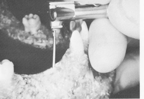
Drilling. A 10: 1 reduction gear contra-angle is often used for inserting the pin implants, since this type contra-angle creates less heat (Fig. 7-23). No
Fig. 7-23. Inserting the pin implant in simulated bone with a 10:1 reduction gear contra-angle.
|
|
Page 267 |
Next Page |
|
Copyright warning: This information is presented here for free for anyone to study online. We own exclusive internet copyrights on all content presented on this website. We use sophisticated technology to identify and legally close down websites that reproduce copyrighted content without permission - so please don’t do it.
|