| Theories and Techniques of Oral Implantology (vol.1) (published 1970) | Dr. Leonard I. Linkow |
|
|
Next Page |
| This is an archival HTML version of this book originally hosted here in 2006. The HTML may not display well on modern browsers. Please view the modern PDF Version for a better viewing experience. |
326 Theories and techniques of oral implantology
acrylic was used for the cementation of the crown to the implant shaft (Fig. 8-45). A final radiograph shows the implant and inlay in position (Fig. 8-46).
Very gratifying results have been obtained with the two-unit splints fabricated in the preceding manner. Also gratifying have been cases in which an implant crown has been attached to inlays made on either side of the implant (Fig. 8-47). In this manner, when the implant is placed in position (Fig. 8-48), it is supported by two inlays attached to the crown covering it (Fig. 8-49).
Case 7
Splinting a single tooth implant with a full crown restoration
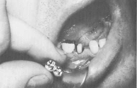
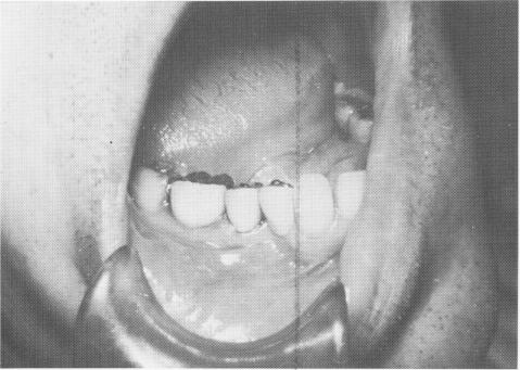
Far more effective than stabilizing with an inlay is splinting the usually stronger distal tooth to the implant with a full crown restoration. The case used as an example is that of a 57-year-old man whose lower right second bicuspid was used as a single abutment for an implant replacement of his first bicuspid. The abutment tooth was prepared for a full crown restoration, and on the next visit a two-unit splint was fabricated, using one of the soft impression materials (Fig. 8-50). (If using copper tube impressions with a modeling compound, this would have been done two visits later.) The splint was tried in the mouth for proper gingival fit, con-tour, and occlusion (Fig. 8-51).
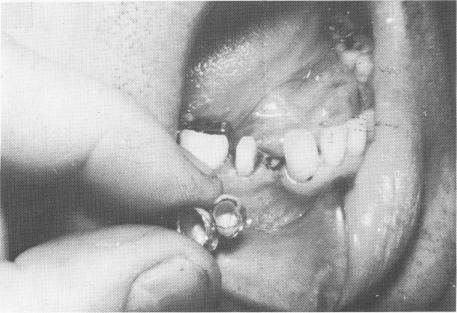
The splint was then removed and the periphery of the crown that covers the implant marked with indelible pencil. Once again the restoration was placed in position and then removed, leaving a ring
Fig. 8-50. A prepared mandibular second bicuspid tooth that will act in symbiosis with a vent-plant to support a two-unit splint is seen.
Fig. 8-51. The splint is fitted into proper position so that all necessary adjustments of occlusion, interproximal fit, and gingival adaptation can be accomplished prior to the insertion of the implant.
Fig. 8-52. The implant site is transferred to the tissue with indelible pencil tracings that were marked along the peripheral border of the corresponding crown.
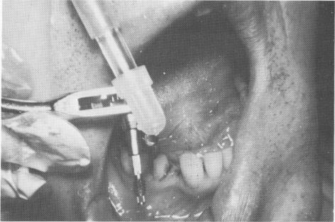
Fig. 8-53. The vent-plant is attached to the ratchet.
|
|
Page 326 |
Next Page |
|
Copyright warning: This information is presented here for free for anyone to study online. We own exclusive internet copyrights on all content presented on this website. We use sophisticated technology to identify and legally close down websites that reproduce copyrighted content without permission - so please don’t do it.
|