| Theories and Techniques of Oral Implantology (vol.1) (published 1970) | Dr. Leonard I. Linkow |
|
|
Next Page |
| This is an archival HTML version of this book originally hosted here in 2006. The HTML may not display well on modern browsers. Please view the modern PDF Version for a better viewing experience. |
Single tooth implants 327
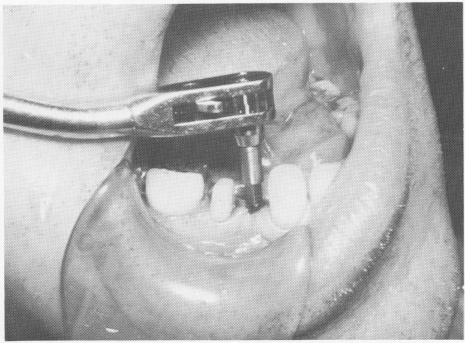
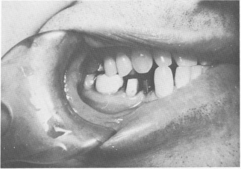
Fig. 8-54. The implant is screwed into position. The prolongator used for this case was longer than usual in order to avoid interference of the occlusal surfaces of the neigh-boring teeth with the head of the ratchet.
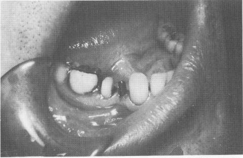
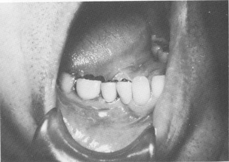
Fig. 8-57. An interchangeable gold coping is placed over the implant shaft.
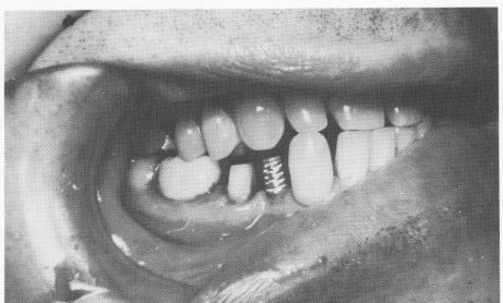
Fig. 8-55. The vent-plant is seen in its proper relationship.
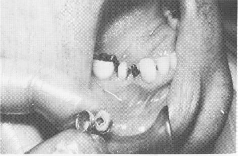
Fig. 8-58. The gold coping is picked up inside the anterior crown with cold cure acrylic.
Fig. 8-56. The implant shaft length should not interfere with the occlusal surfaces of the opposing teeth. It should be short enough to allow enough occlusal gold or porcelain to be included in the restoration.
Fig. 8-59. The two-unit splint is cemented into position with
|
|
Page 327 |
Next Page |
|
Copyright warning: This information is presented here for free for anyone to study online. We own exclusive internet copyrights on all content presented on this website. We use sophisticated technology to identify and legally close down websites that reproduce copyrighted content without permission - so please don’t do it.
|