| Theories and Techniques of Oral Implantology (vol.2) (published 1970) | Dr. Leonard I. Linkow |
|
|
Next Page |
| This is an archival HTML version of this book originally hosted here in 2006. The HTML may not display well on modern browsers. Please view the modern PDF Version for a better viewing experience. |
Maxillary endosseous implant interventions 451
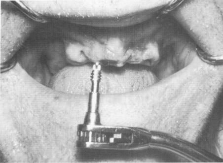
Fig. 10-242. The first vent-plant was screwed into position.
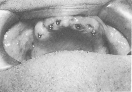
Fig. 10-243. Five internally threaded vent-plants are seen in proper position.
most flush with the tissue covering the alveolar crest (Fig. 10-243). A full mouth plaster impression was taken, and duplicate hollow threaded shafts were included (Fig. 10-244). A master stone model was poured, from which a metal template was fabricated (Fig. 10-245). This was to be held in place by passing small set screws through the template into the internal threads of the implants. The design provided for recessing the small set screws into the
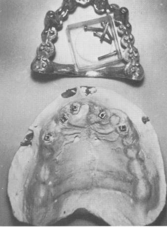
Fig. 10-245. The master stone model and maxillary template are seen. The small set screws that secured the template to the implants are also seen.
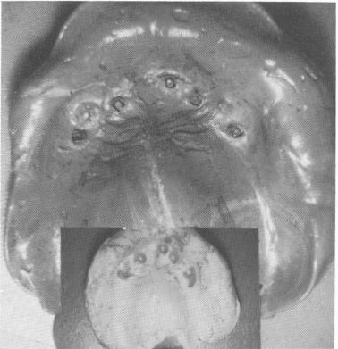
Fig. 10-244. A full arch rubber (top) or plaster impression (bottom) was taken.
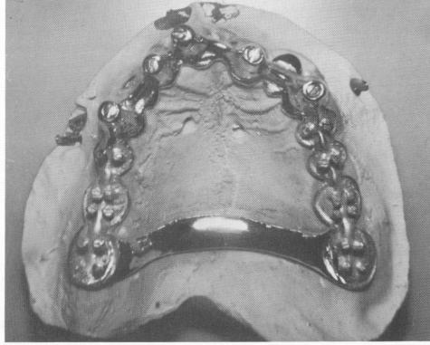
Fig. 10-246. The template was screwed into the internal threads of the duplicate implant shafts on the master stone model.
|
|
Page 451 |
Next Page |
|
Copyright warning: This information is presented here for free for anyone to study online. We own exclusive internet copyrights on all content presented on this website. We use sophisticated technology to identify and legally close down websites that reproduce copyrighted content without permission - so please don’t do it.
|