| Theories and Techniques of Oral Implantology (vol.1) (published 1970) | Dr. Leonard I. Linkow |
|
|
Next Page |
| This is an archival HTML version of this book originally hosted here in 2006. The HTML may not display well on modern browsers. Please view the modern PDF Version for a better viewing experience. |
The evolution of dental implants 167
smaller auxiliary screws are then inserted through drilled holes to lock the transfixation screw heads in place (Fig. 5-61). With the screws in place, the submental wound is closed and bandaged.
Within a few days fabrication of the dental pros-thesis begins. Cast gold crowns with acrylic or porcelain facings cover the implant posts and allow proper parallelism and retention for a removable denture (Fig. 5-62). The denture is constructed in any routine manner to gain its retention from the abutments (Fig. 5-63). Linkow recommends incorporating stress-breaker attachments for the saddle areas posteriorly and splinting the implants to one another anteriorly with a Bolder bar for better stabilization of the implants.
Christensen has observed his patients for over 6 years now and claims that his procedure is successful in stabilizing a mandibular partial or full denture. Because of the design and placement of the implants, no gingival reaction occurs where the posts enter the oral cavity, and no pocket formation has been noted.
PROBLEM SITE IMPLANTS
Problem site implants are specially designed for recognized problem sites such as a maxilla with only a thin layer of alveolar bone in the area of the maxillary sinus, the mandible with too little alveolar bone between its crest and the mandibular canal, and the mandible and maxilla in which the uneven absorption of the alveolar crest has resulted in a knife-edge ridge. All these sites have one thing in common—the amount and/or shape of the alveolar bone contraindicates using any type of upright post endosseous implant. The design problem was to devise other ways of making an implant that was sturdy, compatible with the biomechanical forces operating in the mouth, and easy to insert. The following de-signs represent some of the more successful solutions.
Narrow ridge implants
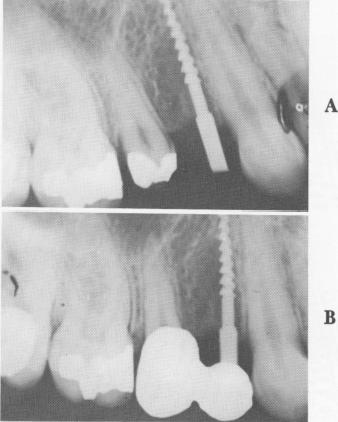
The titanium screw post, designed by Michel Chercheve for a narrow ridge, is threaded along most of the shaft (Fig. 5-64). Above the threaded part is a fairly long, narrow neck that extends from the alveolar crest through the mucosa. Uppermost is a square head that fits exactly into a hand ratchet so that the implant may be worked into the bone, not driven into it. When the implant is in place, its protruding head is bent so that it is parallel to pre-pared teeth and to the abutment posts of other implants (Fig. 5-65).
The narrow ridge implant was designed for knife-
edge ridges and for a small amount of alveolar bone flanking a maxillary sinus or the mandibular canal. If properly stabilized, it stands a good chance of success. However, and this cannot be repeated often enough, an implant must be held secure from all forms of trauma. Because this post is so narrow and has so little surface variation, there is always the danger of its expulsion because of soft tissue invagination. Also, movements of the tongue and lips can cause displacement. The retention that any screw type implant has in bone is directly proportionate to its diameter. Therefore such a narrow screw has very little support from the bone.
Tripod implants
Jacques Scialom invented the highly practical tripod implant, or triplant. He used each of three pins to form a leg of the tripod. Each pin, considered separately, is easy to pull out because of its narrow width and lack of surface detail. However, fused together with acrylic into a triplant, the total implant is practically impossible to remove (Fig. 5-66).
Minor variations in the pins (such as notching the heads to improve locking them together with acrylic) and templates to stabilize the implants and to separate the acrylic from the soft tissues have enhanced the triplant's effectiveness.
The Scialom triplant is particularly successful in circumventing the maxillary sinus or a mandibular canal lying close to the alveolar crest (Fig. 5-67).
Fig. 5-64. The Michel Chercheve narrow ridge implant inserted by Linkow. A, The implant just after insertion; B, the prosthesis in place.
|
|
Page 167 |
Next Page |
|
Copyright warning: This information is presented here for free for anyone to study online. We own exclusive internet copyrights on all content presented on this website. We use sophisticated technology to identify and legally close down websites that reproduce copyrighted content without permission - so please don’t do it.
|