| Theories and Techniques of Oral Implantology (vol.1) (published 1970) | Dr. Leonard I. Linkow |
|
|
Next Page |
| This is an archival HTML version of this book originally hosted here in 2006. The HTML may not display well on modern browsers. Please view the modern PDF Version for a better viewing experience. |
316 Theories and techniques of oral implantology
of centric relation and an opposing jaw alginate impression. The master stone casts were articulated with duplicate shafts in the edentulous areas, as was done in Case 1. In order to give the operator some margin for error in inserting the implants, the shafts were painted with a few coats of nailpolish to make them larger in diameter than the actual implant shafts.
The restorations were fabricated as one-piece castings of two bicuspid acrylic-over-gold crowns (Fig. 8-10). The crowns were tried in the mouth for accuracy of interproximal fit, and all occlusal adjustments were made.
Indelible pencil marks were transferred to the fibromucosal tissue to indicate the implant insertion sites. The No. 6 round burs were drilled through these transferred marks and into the bone (Fig. 8-11) . The round burs were replaced with helical burs that penetrated the bone to the desired depth (Fig. 8-12). Self-tapping vent-plants were then carefully screwed into the bone using a hand ratchet and prolongator attachment (Fig. 8-13).
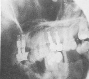
The crowns were cemented over the two protruding implant shafts in the same manner as in Case 1 (Fig. 8-14). However, whereas the implants in Case 1 were left completely unsplinted from the very onset, in this case the implants were immediately ligated to neighboring teeth with soft .010 stainless steel ligature wire (Fig. 8-15). The occlusion once again was carefully checked and all necessary adjustments were made (Fig. 8-16). A post-operative lateral plate roentgenogram of the completed case shows all implants in place (Fig. 8-17).
Fig. 8-17. A lateral plate roentgenogram illustrating the implants.
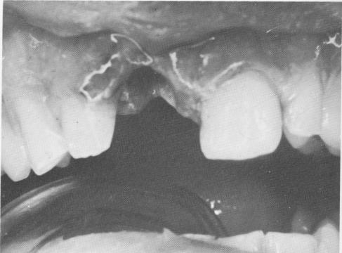
Fig. 8-18. A socket from a recently lost tooth is completely curetted to remove all granulation tissue.
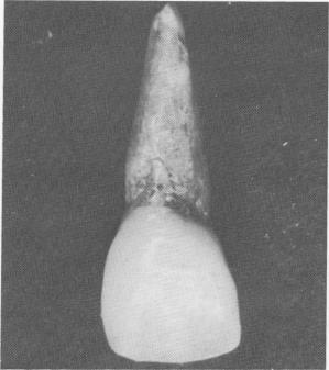
Fig. 8-19. A heat-cured acrylic tooth. The root is processed with 1 part titanium powder to 2 parts acrylic powder so that it can be radiopaque on x-rays. The coronal portion is processed with acrylic powder and liquid only so that the proper color can be matched.
-I
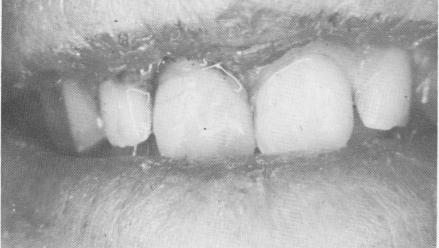
Fig. 8-20. The custom-made tooth fits exactly into the socket. It is usually splinted to both adjacent teeth for several months using .010 stainless steel ligature wire. (From Linkow, L. I.: Histopathological and radiologic studies on endosseous implants, Dent. Concepts 11 [3] :3-13, 1968.)
|
|
Page 316 |
Next Page |
|
Copyright warning: This information is presented here for free for anyone to study online. We own exclusive internet copyrights on all content presented on this website. We use sophisticated technology to identify and legally close down websites that reproduce copyrighted content without permission - so please don’t do it.
|