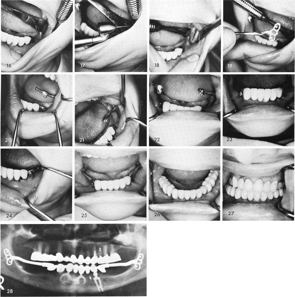
The ramus is exposed and a groove is made on the buccal side, figs. 11, 12, and the blade with its anterior cable is tapped into place so that the cable was tipping upward from the occlusal plane, fig. 13. The hollow tube with its male figure eight lock is fitted to the cable, figs. 14, 15. Steps are repeated on the opposite side, figs. 16, 17, 18, 19, 20, 21, 22. The tubes with the cables are adjusted mesially and distally as they are tapped downward to engage the female locks and then cemented into position, figs. 23, 24. One week later the tissues are healed, fig. 25, and the posterior restorations were cemented over the cables, figs. 26, 27. Fig. 28 shows the post-operative x-ray.