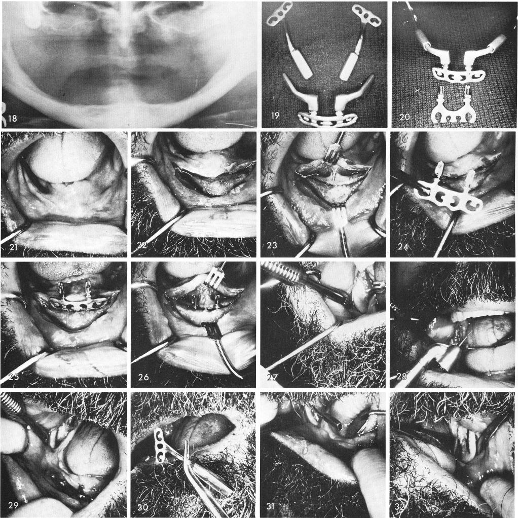
Fig. 18 shows pre-operative x-ray. The five piece system that was used, figs. 19, 20. The clinical view, fig. 21. The anterior tissues were incised and reflected, fig. 22, the groove was made, fig. 23, and the symphyseal blade was placed over the groove and tapped to place, figs. 24, 25, 26. Posteriorly the tissues covering the right ramus were incised, exposing the bone, fig. 27, and with a bayonette type hand piece, fig. 28, the ramus groove was made, fig. 29. The ramus blade was inserted, figs. 30, 31, and then the left ramus groove was made, fig. 32. Fig. 33 shows both hollow tube extensions extending from both ramus blades. The extension arm from the anterior coping was inserted into the posterior hollow tube and the coping tapped downward to fit over