| Theories and Techniques of Oral Implantology (vol.2) (published 1970) | Dr. Leonard I. Linkow |
|
|
Next Page |
| This is an archival HTML version of this book originally hosted here in 2006. The HTML may not display well on modern browsers. Please view the modern PDF Version for a better viewing experience. |
Maxillary endosseous implant interventions 455
and were drilled to the desired depth (Fig. 10-256). Radiographs were taken during the entire procedure.
The vent-plants were then screwed through the template, using the tubes as their guides (Fig. 10-257). Once they were halfway in the bone, the tern-plate was removed to facilitate carefully inserting each implant to its proper depth (Fig. 10-258) .
Quick cure acrylic was placed inside the template tubes, and the template was placed over the Vaseline-coated protruding implant posts. Before the acrylic completely set, the template was removed and left outside the mouth to harden. All excess acrylic on the tissue-bearing side of the template was re-moved, and the template was smoothed and polished. The resulting square-shaped holes inside the acrylic were widened to ease seating the template over the posts. The occlusal and incisal surfaces of
the acrylic were also trimmed and polished flush to the occlusal rims of the tubes.
The template was replaced in the mouth and checked to see if it fit without any impingement from the protruding implant shafts. Posterior radiographs were taken to determine where to make the holes for the triplant pins. The template was removed to make the holes. Then the post type implant's protruding shafts and their corresponding holes in the acrylic were thoroughly dried. Oxyphosphate of zinc cement was placed inside the holes and the template held firmly in position (Fig. 10-259).
The pin implants were drilled through the pre-pared holes in the posterior area of the template (Fig. 10-260), and they were then locked together and to the template with acrylic.
A full maxillary impression, including the entire template, was taken with an elastic impression ma-
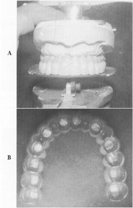
Fig. 10-261. A, The superstructure was carefully balanced on a specially designed occlusal template (Zelnigher), which is adaptable to any three-dimensional articulators. The occlusal planes on both posterior quadrants are geometrically parallel to each other. B, The internal side of the super-structure.
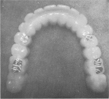
Fig. 10-262. A few gold occlusal stops are sometimes included to slow down the occlusal "wearing down" of the acrylic.
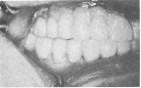
Fig. 10-263. The balanced completed prosthesis.
|
|
Page 455 |
Next Page |
|
Copyright warning: This information is presented here for free for anyone to study online. We own exclusive internet copyrights on all content presented on this website. We use sophisticated technology to identify and legally close down websites that reproduce copyrighted content without permission - so please don’t do it.
|