| Mandibular Implants (published 1977) | Dr. Leonard I. Linkow |
|
|
Next Page |
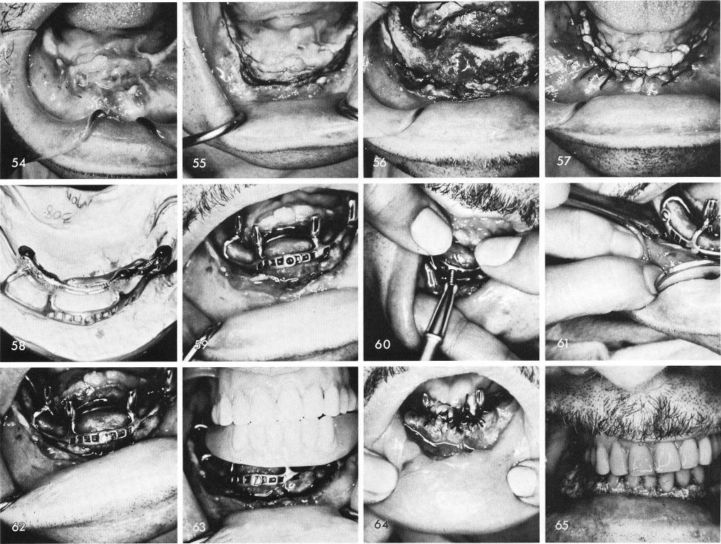
Clinically the tissues were greatly scarred and the floor of the mouth was at the apex of the tissue, fig. 54. The incision, fig. 55, and reflection of the thickened tissues was difficult. As can be seen, fig. 56 shows the complete bony union on the right side. After the impression the tissues were sutured closed, fig. 57, because of poor healing and the pulling away of the tissues after surgery surgery "two" was not performed before six weeks had passed. The subperiosteal implant and superstructure as seen on the master model, fig. 58, and in the mouth, fig. 59. To make sure the implant would not move during the expected slow healing of the scarred tissues Vitallium screws used with a Vitallium screwdriver were used to stabilize the implant, figs. 60, 61, 62.
The temporary stent reveals the asymmetry between the midline of the face and the center of the symphysis represented by the horizontal screw, fig. 63. A tremendous amount of sutures were needed to adapt the tissues to one another as well as accessory incisions in the buccal fold all around the arch, fig. 64. To retard the healing of the accessory incisions a periodontal packing was used and held in place by the temporary stent, fig. 65. Healing was beyond
257
|
|
Page 257 |
Next Page |
|
Copyright warning: This information is presented here for free for anyone to study online. We own exclusive internet copyrights on all content presented on this website. We use sophisticated technology to identify and legally close down websites that reproduce copyrighted content without permission - so please don’t do it.
|